

EcuTek Custom Mapping 01-18
EcuTek custom mapping is available on all turbo models from 01 onwards. On these cars, no longer is the standard ECU a power limiting item, quite the opposite, it can pull together the modifications made to the car and through careful adjustment can release the engines full potential.
Typically this results in a smoother flow of power, earlier boost rise and a vast improvement to the midrange pull. The top end power will depend upon other modifications made to the car. A decat exhaust alone can allow substantial gains from a remap. Economy can also be improved as the overfueling at high load is reduced.
The new age cars from 01 onwards have an excellent Denso ECU, this has more functionality than some aftermarket "performance" items.
Typical functions include map swapping between standard and performance maps whilst driving (on 01 onwards models) gear dependant boost control, temperature controlled boost level to ensure the car is properly warmed up before full power is allowed and much more.
Racerom can be applied to 06 onwards cars, this offers twin maps (economy/power) and also special features such as MAF elimination, flat foot shifting, auto downshift blipping, advanced launch control etc.
This custom mapping is £480
Volume discounts are available on this price and a typical 'group buy' price is £400 depending on the number of cars booked in.
Phone or email for details of the latest offers available.
The above price is for the initial custom mapping which includes the licencing fee for the ECU. Subsequent mapping at a future date of a licenced ECU is £280 if it my own base map or "380 if starting with another tuners base map. For further reading on this product and some excellent tuning information refer to www.ecutek.co.uk
Below is an article originally written by John Banks for SIDC magazine, it offers an insight to the workings of the Subaru ECU.
Open loop – this method mainly uses inputs from the mass airflow (MAF) sensor and engine speed to control the amount of fuel required at higher engine loads – typically when on boost when richer mixtures are required for power and detonation control (see later).
From knowing the amount of air going into the engine a desired air:fuel ratio can be achieved.
A failed MAF sensor leads to poor running, and usually a check engine light and “limp home” mode where engine speed is limited to typically 3000 RPM and boost to 8 PSI.
Unfortunately the MAF sensor can fail on some models in such a way that the ECU does not recognise this, but is supplied with artificially low readings. The consequence of this is that the ECU runs too lean and too much ignition advance.
This can pose a serious threat to the engine from detonation. With a working knock sensor the ECU will sense this detonation and try to control it by adding fuel and retarding the ignition timing, and ultimately dropping the boost pressure again to 8 PSI.
The ECU does similar in a number of situations that threaten the engine, and any such behaviour should be thoroughly investigated.
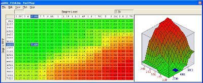
The colourful box below shows a typical fuel map. Engine speed in RPM is down the side, and engine load is across the top. The right hand column of red shows rich fuelling on full load and midrange RPM. The bottom right shows full load at high RPM – very rich. The fuelling moves from lean in the top left corner to rich in the bottom right, the ECU getting to higher loads as boost increases up to about 2800 RPM and then slowly falls away up to 6400 RPM.
The ECU also learns ignition timing from the knock sensor and effectively sculptures these maps over time. Pre 1999 models retard the timing in an area of the map if the knock sensor was ever active. 1999/2000 models will try periodically to advance the ignition again. 2001 and later models run very actively on the knock sensor and adapt very quickly.
The practicality of this is that resetting the ECU should be performed on pre 1999 cars if a higher octane fuel is used or if just recovering from a tank of “bad fuel” as sometimes happens. This will enable the ECU to relearn more appropriate ignition timing for the present fuel. It is not worth resetting later models. On 1999/2000 models, typically after twenty or so miles, the ECU has adapted quite a lot.
There is no need with any car to excessively load the engine on the brakes or by putting four heavy blokes in the car and driving up long hills. If anything excessive load will only expose the car to more detonation and it will learn more pessimistic ignition timing!
It is controlled by a pneumatic feedback system from the compressor outlet and will settle at about 8 PSI. However, the ECU can bleed off some of this air through the wastegate solenoid and thus control the turbo boost depending on throttle position and engine speed.
The turbo, depending on its size, has an efficiency range where is works best. The small TD04L turbo on the 1997 onwards cars gives quick and early spool up but is already losing efficiency after 5000 RPM. Loss of efficiency means more heat and greater exhaust backpressure for the same boost – risk factors for detonation, so you have to be careful with the boost, and all this means less air, less fuel and less torque.
The TD05 on the 1996 and earlier UK cars and the VF series turbos on imports (and the P1, STi Type UK and 22b Type UK) are all considerably bigger, which means they spool up later in the rev range and have more “lag” between pressing the accelerator and producing good torque, but can continue to make good airflow and hence power all the way up to 8000 RPM. Combined with shorter gear ratios these turbos can make for an exhilarating driving experience.
Minimum best torque (MBT) timing is the point to aim for on all engines – practically on a turbocharged engine detonation limits ignition advance before the torque starts to drop off from advancing the timing further. The knock sensor can help to prevent excessive ignition advance in harsh environments where detonation is more likely, and can help to maintain the timing at the compromise point by just being detonation free but producing good power and torque.
Boost pressure – as discussed earlier within the limits of the turbo and intercooler, substantial increases in power and torque can be achieved.
Adjusting the above parameters can give good results whilst eroding slightly the wide safety margins Subaru have left. Enhancing the cooling and breathing of the car by means of upgraded intercoolers/turbos/exhausts allows further safe increases in performance to be achieved, but there is rarely a “free lunch”. Boost pressure cannot just be increased forever without thought to the consequences. At best it will provide no further increases in power because the turbo is just superheating the air. At worst it can result in major engine damage, especially from detonation, which is the big enemy of turbocharged engines as it can be particularly destructive.
If the duty cycle is 0%, do not expect that the boost pressure will be 0 PSI. Under light loads, the boost will be negative (partial vacumm). Also at heavy loads, even if the duty cycle is zero, the boost pressure must overcome the spring tension actin on the wastegate diaphragm before any exhaust gases can pass around the turbo (through the wastegate). In practise, this means that you may see several PSI of boost (perhaps 8-10PSI) even with no solenoid activity.
When people discuss boost pressures, they are generally referring to manifold relative pressure. For vehicles running high boost, it is better to view manifold absolute pressure due to the way in which the data is reported: The manifold relative pressure parameter can only report pressures up to around 19 PSI. Beyond this pressure, the ECU will just report 19 PSI. To get around this limitation, read manifold absolute pressure instead. This parameter will read up to approx 37PSI. Subtracting 14.5 PSI for atmospheric pressure shows that this parameter can convey boost pressures of up to approx. 22 PSI.
As an example... If a car is said to be running 16 PSI of boost, this would be a 'manifold relative pressure' of 16 PSI, or a 'manifold absolute pressure' of 16 + 14.5 = 30.7 PSI. That's 16 PSI relative to the atmosphere, or 30.7 PSI relative to a complete vacuum.
1 atmosphere = 1 Bar = 14.503 PSI. FuellingInjector MillisecondsNumber of milliseconds that each injector is open for for each cylinder cycle (2 revolutions of the crank). To calculate injector duty cycle: Duty Cycle % = RPM * 'Injector ms' / 1200. DeltaDash will also do this conversion for you. If you are regularly seeing over 90% duty, you may need bigger injectors. The injectors must have enough 'head room' too cope with unexpectedly high air flows - these may be caused by overboost, faults and particularly cold weather.
The addition of cone style induction kits, whilst improving top end power and throttle response is known to upset air/fuel ratios. Alteration of the ecu calibration (AKA a remap) is the solution.
The new age cars from 01 onwards have an excellent Denso ECU, this has more functionality than some aftermarket "performance" items.
Typical functions include map swapping between standard and performance maps whilst driving (on 01 onwards models) gear dependant boost control, temperature controlled boost level to ensure the car is properly warmed up before full power is allowed and much more.
Racerom can be applied to 06 onwards cars, this offers twin maps (economy/power) and also special features such as MAF elimination, flat foot shifting, auto downshift blipping, advanced launch control etc.
This custom mapping is £480
Volume discounts are available on this price and a typical 'group buy' price is £400 depending on the number of cars booked in.
Phone or email for details of the latest offers available.
The above price is for the initial custom mapping which includes the licencing fee for the ECU. Subsequent mapping at a future date of a licenced ECU is £280 if it my own base map or "380 if starting with another tuners base map. For further reading on this product and some excellent tuning information refer to www.ecutek.co.uk
Below is an article originally written by John Banks for SIDC magazine, it offers an insight to the workings of the Subaru ECU.
Mysteries of the ECU
The Electronic Control Unit (ECU) we discuss in this article is the “brain” of your engine. It is a computer inside a protective metal box under the carpet in the passenger foot well. Taking information from many sensors, it coordinates the fuel injectors, spark plugs and, where appropriate, turbo boost. We will discuss each of these in turn, along with detonation and tuning for more performance.Fuelling
Closed loop – this method uses the lambda sensor to set the air:fuel mixture to 14.7:1 which is the point for most complete combustion of petrol. This gives good emissions and economy at idle and cruise. It is not useful for high power. A failed lambda sensor is a common reason for MOT emissions failure since the precise 14.7:1 mixture required for catalyst efficiency cannot be maintained.Open loop – this method mainly uses inputs from the mass airflow (MAF) sensor and engine speed to control the amount of fuel required at higher engine loads – typically when on boost when richer mixtures are required for power and detonation control (see later).
From knowing the amount of air going into the engine a desired air:fuel ratio can be achieved.
A failed MAF sensor leads to poor running, and usually a check engine light and “limp home” mode where engine speed is limited to typically 3000 RPM and boost to 8 PSI.
Unfortunately the MAF sensor can fail on some models in such a way that the ECU does not recognise this, but is supplied with artificially low readings. The consequence of this is that the ECU runs too lean and too much ignition advance.
This can pose a serious threat to the engine from detonation. With a working knock sensor the ECU will sense this detonation and try to control it by adding fuel and retarding the ignition timing, and ultimately dropping the boost pressure again to 8 PSI.
The ECU does similar in a number of situations that threaten the engine, and any such behaviour should be thoroughly investigated.
The colourful box below shows a typical fuel map. Engine speed in RPM is down the side, and engine load is across the top. The right hand column of red shows rich fuelling on full load and midrange RPM. The bottom right shows full load at high RPM – very rich. The fuelling moves from lean in the top left corner to rich in the bottom right, the ECU getting to higher loads as boost increases up to about 2800 RPM and then slowly falls away up to 6400 RPM.
Ignition Timing
This is determined mainly from the MAF sensor and the engine speed. There are maps for high octane and low octane fuels and the ECU selects between them depending on knock sensor activity.The ECU also learns ignition timing from the knock sensor and effectively sculptures these maps over time. Pre 1999 models retard the timing in an area of the map if the knock sensor was ever active. 1999/2000 models will try periodically to advance the ignition again. 2001 and later models run very actively on the knock sensor and adapt very quickly.
The practicality of this is that resetting the ECU should be performed on pre 1999 cars if a higher octane fuel is used or if just recovering from a tank of “bad fuel” as sometimes happens. This will enable the ECU to relearn more appropriate ignition timing for the present fuel. It is not worth resetting later models. On 1999/2000 models, typically after twenty or so miles, the ECU has adapted quite a lot.
There is no need with any car to excessively load the engine on the brakes or by putting four heavy blokes in the car and driving up long hills. If anything excessive load will only expose the car to more detonation and it will learn more pessimistic ignition timing!
Boost Control
The turbo is a compressor that is driven by the exhaust gases. The wastegate diverts (“wastes”) these exhaust gases to regulate the speed of the turbo.It is controlled by a pneumatic feedback system from the compressor outlet and will settle at about 8 PSI. However, the ECU can bleed off some of this air through the wastegate solenoid and thus control the turbo boost depending on throttle position and engine speed.
The turbo, depending on its size, has an efficiency range where is works best. The small TD04L turbo on the 1997 onwards cars gives quick and early spool up but is already losing efficiency after 5000 RPM. Loss of efficiency means more heat and greater exhaust backpressure for the same boost – risk factors for detonation, so you have to be careful with the boost, and all this means less air, less fuel and less torque.
The TD05 on the 1996 and earlier UK cars and the VF series turbos on imports (and the P1, STi Type UK and 22b Type UK) are all considerably bigger, which means they spool up later in the rev range and have more “lag” between pressing the accelerator and producing good torque, but can continue to make good airflow and hence power all the way up to 8000 RPM. Combined with shorter gear ratios these turbos can make for an exhilarating driving experience.
Detonation
There are many vicious circles surrounding the complex topic of detonation, but it is public enemy number one for turbocharged engines, and can lead to serious damage. The problem is that the best torque is usually obtained from a turbocharged engine boost by running the ignition timing at the threshold of detonation occurring. Hence the use of the knock sensor as discussed earlier to help walk this tightrope safely. >ECU Tuning for more power and torque
Typically many Subarus run very rich 10:1 air:fuel mixtures which helps cylinder cooling and shifts the knock point favourably and allows more ignition advance. It is a compromise. Some report gains of 20 bhp from leaning out to 12:1, but the risks can be reduced by better thermal management – e.g. using a larger turbo and a front mounted intercooler.Minimum best torque (MBT) timing is the point to aim for on all engines – practically on a turbocharged engine detonation limits ignition advance before the torque starts to drop off from advancing the timing further. The knock sensor can help to prevent excessive ignition advance in harsh environments where detonation is more likely, and can help to maintain the timing at the compromise point by just being detonation free but producing good power and torque.
Boost pressure – as discussed earlier within the limits of the turbo and intercooler, substantial increases in power and torque can be achieved.
Adjusting the above parameters can give good results whilst eroding slightly the wide safety margins Subaru have left. Enhancing the cooling and breathing of the car by means of upgraded intercoolers/turbos/exhausts allows further safe increases in performance to be achieved, but there is rarely a “free lunch”. Boost pressure cannot just be increased forever without thought to the consequences. At best it will provide no further increases in power because the turbo is just superheating the air. At worst it can result in major engine damage, especially from detonation, which is the big enemy of turbocharged engines as it can be particularly destructive.
ECU Diagnostics
OEM ECU Diagnostic DataThis page details some of the more important diagnostic data that may be retrieved from Subaru vehicles via DeltaDash or the Subaru 'Select Monitor'. It also explains the symptoms of some common problems.Analogue Parameters
Analogue parameters are continuously varying data values that may be retrieved from the ECU. These values generally represent pressures, voltages and temperatures. Boost ControlPrimary & Secondary ControlWastegate solenoid valve duty cycles. Primary and secondary refers to whether it is the wastegate duty for the first or second turbo charger. If the vehicle only has one turbo, this will be primary control. The higher the duty cycle the more pressurised air is bled away from the diaphragm of the wastegate actuator. The spring opposing the diaphragm forces the wastegate to close. This forces more exhaust gases to pass through the turbine - more duty encourages higher boost pressures. Low duty restricts boost by allowing the pressurised air to act on the diaphragm, pushing open the wastegate, allowing exhaust gases to bypass the turbine.If the duty cycle is 0%, do not expect that the boost pressure will be 0 PSI. Under light loads, the boost will be negative (partial vacumm). Also at heavy loads, even if the duty cycle is zero, the boost pressure must overcome the spring tension actin on the wastegate diaphragm before any exhaust gases can pass around the turbo (through the wastegate). In practise, this means that you may see several PSI of boost (perhaps 8-10PSI) even with no solenoid activity.
Atmospheric Pressure
At sea level, this should be around a bar or 14.5 PSI. On some vehicles, the value is not updated continuously, since a single pressure sensor is shared for reading both manifold and atmospheric pressures, a solenoid being using to switch the input to the sensor. >Manifold Absolute & Relative Pressure
This is boost pressure, and may be represented as absolute or relative, depending on the ECU - some ECUs report both parameters, whilst some only report one. Absolute pressure in the manifold is relative to a vacuum. Subtract approx 14.5 PSI to get relative pressure. When boost pressure in the manifold is shown as relative to atmospheric pressure, negative values represent partial vacuums in the manifold. >Intake Air Temperature
Temperature of air drawn into the engine for combustion. Generally measured at the point of entry to the air filter. This will not give an indication of charge temperature. However intake temperature is useful to the ECU for determination of the wastegate duty cycle required to produce a given boost pressure. High boost pressures may be attained with lower wastegate duty cycles when the IAT is low.When people discuss boost pressures, they are generally referring to manifold relative pressure. For vehicles running high boost, it is better to view manifold absolute pressure due to the way in which the data is reported: The manifold relative pressure parameter can only report pressures up to around 19 PSI. Beyond this pressure, the ECU will just report 19 PSI. To get around this limitation, read manifold absolute pressure instead. This parameter will read up to approx 37PSI. Subtracting 14.5 PSI for atmospheric pressure shows that this parameter can convey boost pressures of up to approx. 22 PSI.
As an example... If a car is said to be running 16 PSI of boost, this would be a 'manifold relative pressure' of 16 PSI, or a 'manifold absolute pressure' of 16 + 14.5 = 30.7 PSI. That's 16 PSI relative to the atmosphere, or 30.7 PSI relative to a complete vacuum.
1 atmosphere = 1 Bar = 14.503 PSI. FuellingInjector MillisecondsNumber of milliseconds that each injector is open for for each cylinder cycle (2 revolutions of the crank). To calculate injector duty cycle: Duty Cycle % = RPM * 'Injector ms' / 1200. DeltaDash will also do this conversion for you. If you are regularly seeing over 90% duty, you may need bigger injectors. The injectors must have enough 'head room' too cope with unexpectedly high air flows - these may be caused by overboost, faults and particularly cold weather.
A/F Sensor #1 Current & Resistance
These parameters show the current passing through the front air/fuel sensor and the sensor's resistance. These are inputs used to calculate front sensor air/fuel ratio.A/F Sensor #1
Short term correction percentage applied to fuelling based on the output of the front air/fuel sensor.A/F Correction #3
Short term correction percentage applied to fuelling based on the output of the rear O2 sensor. This sensor is after any catalytic converters and helps to fine tune the fuel mixture to minimise emissions.A/F Learning #1
Long term correction percentage applied to fuelling based on feedback from front and rear sensors.Front & Rear O2 Sensors
These parameters report the output voltage of the O2 sensors. Early vehicles tend to have a single 'Front O2 Sensor', whereas newer vehicles have both a 'Front A/F Sensor' and a 'Rear O2 Sensor'. These sensors do not report an accurate air/fuel ratio, but instead provide a rich/lean signal to the ECU. Their output voltages switches sharply as the AFR crosses the stoichiometric ratio. Values of approx 0 to 0.9 Volts are normal. 0 being lean, 0.9 being very rich. The sensor voltage will oscillate between these extremes when under closed loop control. Under high loads, the voltage should never drop below 0.7 Volts. If it does, this means that the fuel mixture is too lean when on boost. Quite possibly there is a fault with the air flow sensor.The addition of cone style induction kits, whilst improving top end power and throttle response is known to upset air/fuel ratios. Alteration of the ecu calibration (AKA a remap) is the solution.